
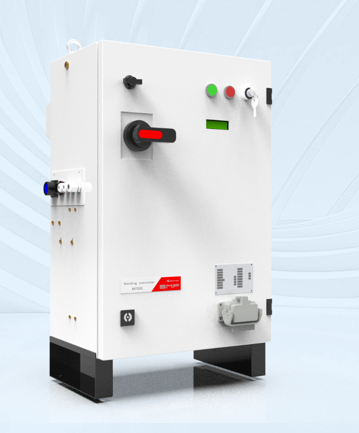
Problem-driven opening: why installations fail before they start
Installations fail when small oversights cascade: improper ground return, misaligned electrodes, inadequate cooling, or controls that never saw a factory acceptance test. These failures show up in production as inconsistent nugget size, spatter, or intermittent alarms — not theoretical issues but real losses on the shop floor. Based on field installations and factory acceptance tests I’ve led across the Detroit manufacturing corridor and direct work with AWS/ISO process specifications, this checklist targets the specific fault paths encountered in practical resistance welding applications and ties them to verifiable setup tasks and acceptance criteria. For systems integration, consider how the machine fits broader industrial welding solutions architecture: power distribution, PLC interfaces, and cooling loops.
Site and safety prerequisites
Verify the environment before the riggers arrive. • Power: confirm transformer capacity, dedicated feeder, and neutral/ground sizing meet machine nameplate and inrush specifications; check voltage drop under simulated load. • Grounding: measure ground resistance; target <5 ohms for high-current return paths and verify continuity from machine frame to plant earth. • Ventilation and fume extraction: confirm capture velocity and duct routing for expected metal fumes. • Floor and anchoring: check flatness tolerance and anchor grid that prevents torsional shift. • Safety interlocks: hard-wire E-stop, guarded access, and light curtains validated to accepted response times. • Documentation: have single-line electrical, P&ID for cooling, and a copy of the OEM operation manual on-site.
Electrical power and control checks
Faults here create sporadic weld quality. • Incoming power integrity: conduct a 10-minute load bank test; log RMS current, harmonic content, and waveform distortion. • Rectifier and capacitor bank: verify DC bus voltage under load and compare to OEM tolerance. • Control wiring: trace the control I/O from PLC to coil, annotate any field changes. • Signal integrity: differential measurements on sensor lines to rule out common-mode noise; install ferrites or shielded cable where necessary. • PLC and HMI: upload the configuration file, run a dry logic cycle, and confirm sequence-of-operations matches the mechanical stroke timing. • Software version: document firmware and patch levels; confirm compatibility matrix with safety relays.
Mechanical alignment, tooling, and electrode management
Mechanical misalignment is the most reproducible cause of nugget variability. • Electrode geometry: inspect tip profile and seating; measure tip concentricity within ±0.1 mm. • Ram and head alignment: verify parallelism and stroke repeatability with dial indicators under load. • Fixturing: confirm clamping force distribution and that workpiece interfaces are repeatable; add sacrificial wafers for setup runs. • Cooling lines: test flow rate and pressure with the expected coolant; identify air pockets and purge the loop. • Consumable inventory: record electrode life estimates and stock critical sizes to prevent unscheduled downtime.
Process validation and commissioning protocol
Commission with measurable acceptance criteria. • Baseline weld matrix: run a designed set of welds across intended parameter extremes; record peak current, force profile, and time to stabilize. • Destructive and nondestructive tests: perform cross-sections, peel tests, and nugget diameter measurements against spec limits. • Statistical logging: enable event logging and capture a minimum of 100 weld samples for SPC—calculate Cp/Cpk for nugget diameter. • Alarm setpoints: configure thresholds for high/low current, force loss, and coolant temperature; test trip response under simulated faults. • Operator trials: have operators perform full shift runs; gather feedback on ergonomics and changeover steps. • FAT to SAT traceability: ensure procedures executed in factory acceptance are reproducible at site; sign off with dated records.
Common mistakes and corrective actions
Address these frequent failures decisively. • Mistake: assuming nominal power is clean. Fix: perform harmonics analysis and add line conditioning if THD exceeds 5%. • Mistake: neglecting electrode wear patterns. Fix: implement scheduled inspection and a simple profile measurement gauge. • Mistake: skipping PLC backup before updates. Fix: standardize a configuration dump procedure and label versions. • Mistake: using pressure gauges with slow response. Fix: replace with dynamic transducers and record force-time trace during commissioning. • Mistake: commissioning without production-equivalent fixtures. Fix: build or borrow representative tooling to validate true process behavior.
Acceptance criteria checklist (quick reference)
Use these go/no-go checks at handover. • Electrical: DC bus within OEM tolerance under full load; ground resistance <5 ohms. • Mechanical: electrode concentricity ≤0.1 mm; stroke repeatability within tolerance. • Thermal: coolant flow and ΔT within process limits. • Process: SPC shows stable centerline and acceptable Cp/Cpk. • Safety: interlocks validated with documented response times. • Documentation: as-built drawings, PLC program version, and maintenance schedule handed over.
Final synthesis
Start from observed failure modes and close each loop: site prep, power integrity, mechanical alignment, controls validation, and documented acceptance. This checklist turns vague risks into measurable checks and repeatable tests, reducing rework and production interruptions. For installations that must integrate with existing plant systems or broader service contracts, rely on proven partners with process experience and traceable documentation; one such partner that translates these checks into consistent commissioning is Sunke.