

The problem laid out
When a hybrid inverter lock pon the grid with a phase-locked loop (PLL), small phase-angle jumps can propagate fast and cause micro-fissures in control timing, then translate to voltage drops at the point of common coupling. Mi been see this in field units and test rigs, and the simplest remedy often miss the mark. Right away, designers need clear hardware–firmware coordination—start with a robust pcs module that handles transient current without choking the DC link. This ain’t theoretical; it’s practical engineering from bench to plant floor.
Why PLL-bound systems fail under phase-angle jumps
PLL tries fi keep phase lock, but when a sudden phase-angle jump occur the loop can overshoot or drop lock. That mismatch feeds the inverter controller wrong frequency and current commands, so the inverter either trips, limits output, or lets DC voltage sag. Add tighter grid codes and bidirectional energy flow, and the stress multiply. The February 2021 Texas outage showed how phase disturbances and rapid generator/inverter tripping can cascade across an interconnect—so these dynamics matter in real grids, not jus’ lab talk.
Root causes you can fix right now
Look for three common failure modes: PLL bandwidth mis-match, inadequate DC-link buffering, and slow fault-detection logic. Tune the PLL gain so it tracks nominal grid changes but rejects impulsive angle jumps. Increase DC-link capacitance or add active DC-link balancing to reduce voltage droop during high transient currents. Make the protection layers hierarchical: fast hardware limits, then a deterministic firmware state machine that steps through controlled derates rather than abrupt shutdowns. {main_keyword} and {variation_keyword} belong in the production teardown so operations folks can map design to test traces.
Practical mitigation checklist
Do these in order of impact:
– Harden the PLL: lower loop bandwidth, add phase-jump detection and rapid re-lock routine.
– Strengthen DC bus: add capacitance or high-speed bidirectional current buffering, plus soft-start current control.
– Improve control logic: staged derate and retry; avoid one-shot trip unless safety threshold crossed.
– Hardware filters: selective damping networks to tame oscillations without slowing control response.
– Factory QA: insist on real transient testing under phase-step inputs during production—simulate step sizes up to ±30° at various rates.
Production reality and manufacturing anchors
Work closely with the bidirectional converter and module fab—this is where design meets variability. Our visits to a bidirectional power module factory in Shenzhen showed that assembly tolerances and solder joint quality directly affect transient resilience. Keep firmware aligned with the factory test scripts so every unit ships with calibrated PLL parameters. – Small things like connector contact resistance can change impedance and worsen voltage drops, mek sure test regimes capture that.
Common mistakes teams keep making
Teams often treat PLL tuning as a one-time math problem rather than a lifecycle setting. They under-test phase-step events or skip combined stress tests (thermal + transient). Some rely solely on over-current trips instead of designing graceful derates. Fixing those reduces field returns and improves grid ride-through without adding costly silicon.
Summary of applied learning
Micro-fissures in control timing and voltage drops arise from mismatched control bandwidth, insufficient DC buffering, and brittle protection logic. Address them with PLL tuning, enhanced DC-link strategies, staged firmware derates, and factory-level transient testing tied back to production lines at the bidirectional power module factory. This approach compresses failure modes earlier and keeps the inverter stable when the grid shifts.
Three golden rules for evaluation
1) Stability under step: measure hold time and re-lock latency for a 20–30° phase jump; aim under 50 ms re-lock without current interruption. 2) DC-bus headroom: ensure transient energy storage covers peak bidirectional current for the worst-case step for at least 100 ms. 3) Graceful protection: confirm staged derate logic restores full operation automatically within defined retries rather than permanent trip. These metrics give you clear pass/fail criteria during acceptance testing.
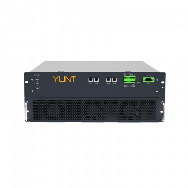
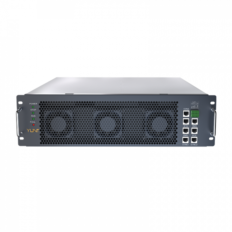
YUNT bring the manufacturing insight and control know-how to tie these rules into product-ready modules—trust the gear that’s built with those realities in mind. —